The primary path of a use case describes the sequence of interactions between the actor(s) and the system that results in the initiating actor's goal being reached. Usually the use case name is chosen so that it reflects the initiating actor's goal when invoking this use case.

When editing a use case, a lot of the high-level primary path information has already been entered. It is possible to explicitly select the primary path for a use case in the Use Case Editor, and this enables you to edit some additional fields that you could not edit when editing the basic use case description.

First, if the use case was in an extension relationship from another use case, it is possible to describe in words where in the parent use case this extension use case branches off the parent's path. The condition that must be true in order for this child use case to begin can be specified as a use case precondition, and a description of the remerge point (if any) back into the parent use case's path can be given. Note that omission of a remerge point description assumes that the return point is at the step immediately after the extension point, hence a description should be given if the point of resumption in the parent use case is anywhere else, or the parent is never returned to.

The brief/casual use case description in the path panel however is merely a duplicate of the primary path description from the main use case editing panel.

To navigate to the primary path editing panel, navigate first to the use case whose primary path you wish to edit, in the tree view at the left of the main window. Next, expand the '+' alongside the selected use case name, and the list of associated actors and paths within that use case will appear beneath the use case. Select the path labelled 'Primary path'. The editing panel will appear to the right:

To add an alternative path to a use case, navigate to the use case in the tree view at the left of the main window, then click the '+' to expand the paths and actors under the selected use case.

From the main menu select Edit | Add path to create a new child alternative path under the selected use case, or click the 'Add path' toolbar button as indicated by the red arrow in the screenshot below. The new alternative path editing panel appears to the right of the tree view, with the new path selected (highlit in red) in the tree view:

Note that the new path has a temporary descriptive name of 'Alt path 1' in the tree view. This is because you have not provided a description of the extension point for the new path yet, nor a description of the branch condition that causes this alternative path to be taken.

Provide a brief description of where this new path branches off another existing path, and a description of what must be true for the alternative path to be taken. Once you move the focus from these input text controls, the name of the alternative path will automatically change to the format '<extension point description> if <branch condition description>'.

You can now provide a description of the steps in the alternative path in the 'Brief/casual description' field, and a description of where the alternative path remerges onto the originating path in the field labelled 'Remerge point'. A completed new alternative path is shown below:

Although not shown in the two screenshots on this page, it is now also possible to specify whether the alternative path is a concurrent, parallel sequence of interactions, or the more conventional 'one or the other' branch in the sequence of interactions that might be captured. When an alternative path is flagged as being concurrent by checking a check box near the top of this page, it means that the sequence of interactions between users and the system for the alternative path are taking place independently of those on the originating path. At the end of the alternative path, both sequences have to reach the merge point before the use case can proceed with the subsequent step. Hence this would be a rendez-vous or synchronisation point in the use case.

Concurrent paths are useful when modelling business processes with use cases, where several business processes might well be executing independently of each other, but need to synchronise at key points in the process.

To edit an existing alternative path in a use case, navigate to the use case in the tree view at the left of the main window, then click the '+' to expand the paths and actors under the selected use case. Select the alternative path that you wish to edit.

You can now edit the brief description of where this path branches off its existing parent path, and can edit the description of what must be true for the alternative path to be taken. Once you move the focus from these input text controls, the name of the alternative path will automatically update to the format '<extension point description> if <branch condition description>'.

You can also edit the description of the steps in the alternative path in the 'Brief/casual description' field, and a description of where the alternative path remerges onto the originating path in the field labelled 'Remerge point'.

To delete an existing alternative path in a use case, navigate to the use case in the tree view at the left of the main window, then click the '+' to expand the paths and actors under the selected use case. Select the alternative path that you wish to delete.

You can either select Edit | Delete path from the main menu, or click on the delete path button on the toolbar as shown below:

Note that a confirmation dialog appears to make sure you intended to delete this path. This is because your child path may be referred to by other paths, or maybe even by other use cases that are in an extension relationship with this use case. Make sure these dependencies are removed before deleting a path from a use case.

Note too that you will not be able to delete the primary path of a use case, for obvious reasons!

When producing detailed use case descriptions, rather than using informal descriptions of the sequences of interactions in paragraph form, it may be more useful to describe the sequences as lists of numbered steps. This has a number of advantages. First, it is easier to see the sequential nature of the use case paths. Second, since the steps are numbered, it is much easier to identify extension and remerge points, because they can now be referred to jst by their step number. Lastly, by describing a use case using the numbered step approach, the Use Case Editor is able to automatically generate activity diagrams showing a use case's primary and alternative paths on a single diagram.

To edit the steps for a primary or alternative path, navigate to the path you wish to edit in the tree view at the left of the main window. Once there, click on the 'Detailed steps' tab at the top of the path editing panel at the right of the main window. A screen shot of this window for a path whose detailed steps have already been filled in is given below:

A description of how to use the controls on this panel now follows, assuming that you start with no steps in the grid at all. Initially you will not be able to use the Append, Insert or Delete buttons, as you need to specify the extension point and remerge point first.

In the 'Extends use case <use case name> after' drop down, select the step number in an existing path after which the alternative path branches and does its own alternative steps. If this is the primary path for a use case, this extension step is not needed.

In the 'Rejoins use case <use case name> at step' drop down, select the step at which your alternative path will resume execution in the primary path when the alternative path is over. Note that if your alternative path is also an alternative end to the use case, you should select 'Ends use case' from the drop down.

Having selected these two items, the three step editing buttons at the bottom of the panel will now be enabled so that you can start adding steps. The function of these buttons is described below.

Append button

This button always appends one new empty step at the bottom of the use case. It does not append after the currently selected step in the step grid.

Insert button

This button inserts an empty step above the currently selected step in the grid. Make sure you select a step in the grid first, so that the newly inserted step is put at the right point in the sequence. Note too that insertion of a step will update all the step numbering. This is automatically consistent, meaning that if a step number is changed while editing, all child paths together with their extension and remerge step numbers will be automatically updated too.

Delete button

This deletes the currently selected step in the grid. Deletion of a step will also update all the step numbering. This is automatically consistent, meaning that if a step number is changed while editing, all child paths together with their extension and remerge step numbers will be automatically updated too.

Note that the only field you need to edit in the grid is the description field. The step numbers are provided automatically by the tool. The include column will be explained below.

Building include relationships

An include relationship exists where one use case invokes the steps of another use case at some point in one of its own sequences of steps. The included use case is run at that point as if it were a single step in the parent use case. Include relationships are mainly employed where two or more use cases have the same common subsequences of steps. By factoring these common sequences out into included use cases, the steps need only be described in one place in the model.

To build an include relationship, you need to identify which step in the parent use case makes a 'call' to the included use case, thereby running its sequence(s) of steps. To do this, navigate to the appropriate primary or alternative path in the parent use case, and select the detailed steps view as described above.

Insert or append a new step, and give it a description that explains this step is an invocation of a child use case, giving the name of the child use case that is being invoked.

While the same new step is still selected, click the <<include>> button at the bottom of the grid. A dialog appears, as shown in the screenshot below:

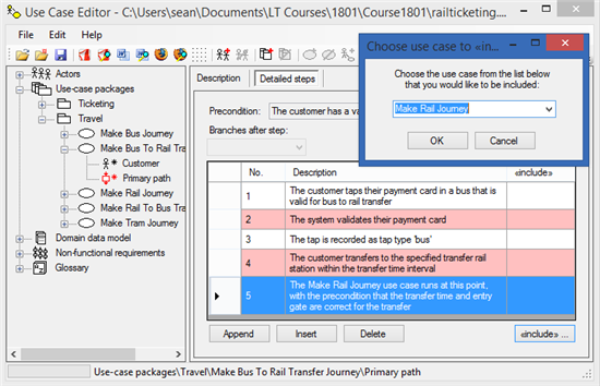
In this dialog box, select the use case that is to be included from the drop down list of use case names, then click OK. To disconnect an include relationship, merely select the empty entry at the top of the drop down list, and click OK.

The name of the included use case will now appear in the cell at the right of the currently selected step in the grid.

Building extend relationships

An extension relationship exists where at some point in a parent use case, the user makes a selection or some condition becomes true, that causes a second use case to be run as a nested use case inside the aprent use case. Thus extension use cases are always launched from within another parent use case, and are always conditional on some trigger in the parent use case.

Extensions are always built from within the extension use case, and refer back to the parent they extend. To makr a use case as being an exteions of another, you will need to identify the parent use case being extended, the condition that must be true for the extension use case to be run nested inside the steps of the parent, and the extension point in the parent.

First, let us assume you have already selected the use case that will be an extension of another. This means the use case editing panel will be appearing on the right of the tree view in the main window of the Use Case Editor.

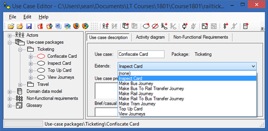
From the Extends drop down select the name of the use case that your currently selected use case will be extending:

Now in the tree view control, expand the current use case node by clicking the '+' alongside the use case name, then click on the 'Primary path' that appears. This will change the panel on the right to show the path editing panel. Make sure you select the 'Description' tab in the panel rather than the 'Detailed steps' tab:

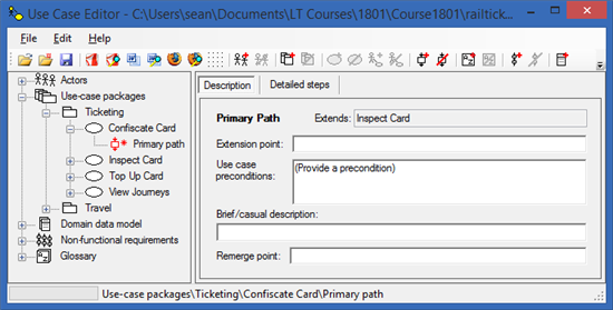
In the editing panel, provide a textual description of the extension point. This should explain briefly where in the originating use case this nested child use case might begin to run.

Provide also a text description of what trigger or condition would cause this extension use case to run at that point in the parent. If this condition is not satisfied at that point, the extension use case will be skipped entirely.

You should also provide the brief primary path description for the extension use case, and the optional remerge point back in the parent use case in the remaining two fields of this editing panel.

Now select the 'Detailed steps' tab. You will notice that the precondition has been copied from the previous editing panel (it cannot be edited in this panel). You will also notice that the names of the two drop downs beneath the precondition have been changed to reflect the fact that they are extending or rejoining the named use case that this child use case is extending:

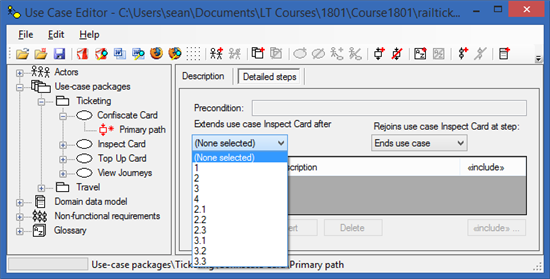
Select the step number in the parent use case that this extension use case follows, from the list of steps in the left hand drop down (as shown in the example above). You will probably have to go and inspect the parent use case's detailed steps to know exactly what step number this should be.

Select the step number in the parent use case at which the child use case returns control to the parent, from the list of steps in the right hand drop down control. Alternatively you can just select 'Ends use case' if control never returns to the parent, but the two use cases end here. In most cases the norm is that the parent is resumed at the step immediately following the step at which it branched. However, you have the flexibility to select a different remerge point in this tool.

At this point the Append, Insert and Delete step buttons will have been enabled beneath the grid, meaning you are now able to append or insert detailed steps for the new child use case in the usual way.

The Use Case Editor builds activity diagrams automatically from the paths and detailed steps for a use case. Assuming you have been adding detailed numbered steps to one or more paths in your use case, you can view the activity diagram at any time. Navigate to the use case whose activity diagram you wish to view in the tree view, then select the 'Activity diagram' tab in the editing panel on the right:

You will not be able to add steps or paths by editing the diagram directly. This tool deliberately does not let you add items to diagrams and then set their descriptive properties afterwards. By making you enter the descriptions, and then autogenerating the diagrams, the tool guarantees that the diagrams match the descriptive text, and that you actually enter some descriptive text rather than just generate diagrams with no context!

Manipulating activity diagrams

Although the content of the diagrams can only be set by editing the model descriptions, the layout can be adjusted from within the diagram pane.

If you click on an entry, exit, activity, branch or merge element in the diagram, the corresponding item changes colour to red to indicate it has been selected. The item can now be dragged to a different location on the screen. Any connectors that link to the dragged item will be adjusted so that they remain connected to the dragged item.

If you double-click an activity box, the Use Case Editor will jump to the editing page for the corresponding step within its parent path, and highlight the step you double-clicked in the grid of step descriptions.

It is possible to reroute the connectors between items. If you click on a connection, the connection line will become red to indicate it has been selected. You may now right click on the connector and a pop-up menu will appear:

Note that if the right mouse button is clicked on a corner selection grip (the red rectangle at the bend in the connector), the 'Insert bend' menu item is replaced with 'Remove bend'. Select all will highlight the whole diagram in red, allowing you to drag everything on the page. Insert bend will allow you to introduce new bends to the connector so that it can be routed around obstacles on the diagram. Auto Layout lets the Use Case Editor automatically layout the diagram using an internal default algorithm. Note if you select this, any manual layouts you made will be lost. There is no 'undo' for this layout window! As a rule, it is best to use auto layout until you are convinced your model is stable. Then as a last finessing step, adjust the layout of the activity diagrams before publication of output documents.

Note too that once a connector has been highlighted, the line itself may be dragged, or by dragging the rectangular grips you can relocate the ends of each line segment. Experiment with dragging connectors, and with inserting or removing bends to familiarise yourself with the layout tools.

Snap to grid

By default the layout tool snaps graphical elements to a grid that has 16 pixel resolution. This makes it easy to keep lines horizontal and vertical, as well as helps to align actors and use case symbols. The grid resolution can be changed to 8, 16, 24, or 32 pixel resolution as well as being switched off altogether. To change the grid resolution select Edit | Grid spacing ... from the main menu, or click the corresponding toolbar button as shown in the screenshot below: