The distinction between a domain model type and a domain model entity or class is explained elsewhere

Here we are concerned with how we add them to the current model's domain data model. First navigate to the data model itself, by lciking on the top-level node 'Domain data model' in the tree view control at the left of the main window. This right hand panel will now be populated with a list of the entities and types known about in the model:

Note that the grid contains three columns. The left column gives the type or entity name. The middle column gives a description of the corresponding entity or type. The right column has a checkbox to indicate whether the item is an entity or a type. The presence of a tick means it is an entity (or class in object-oriented terminology). The absence of a tick means it is a simple type.

To add a new type or class to the domain data model, select Edit | Add class from the main menu, or click the 'Add class' button on the toolbar as indicated by the red arrow in the screenshot below. This will cause a new class or type to be created with the name ClassOrTypeN where N is a possibly absent number. This is unlikely to be the type name you want, so you should change it to a meaningful class or entity/class name immediately:

Once you have changed the name of the type or entity, provide a meaningful description of it in the description box. Typical things that go into this description might be: the meaning or interpretation of the type; the circumstances under which it might be created or deleted as a data item; any constraints or dependencies imposed on its possible data values; qualifying statements about particular interpretations that have led to misunderstandings about its values in the past; etc.

If the type is a simple type with no further decomposable structure, leave the 'Type' radio button selected.

If the type is really an entity or class, for which you will need to define further nested members making it into a compound data type, click the 'Class' radio button instead. Two grids will now appear at the bottom of the editing panel where the nested data members and other entities involved in relationships with this entity will ultimately be listed:

To edit a type or a class, you first need to select the type or class (entity) you want to edit. From the tree view at the left of the main window, click the '+' alongside the top level node named 'Domain data model' to see the list of types and classes known about by the model. Now click on one of the type or class names from the list, and the right panel will be populated with the editing panel for that type or class. The content can then be edited as described in the 'Adding Types and Classes' section above.

To delete a type or class/entity from the data model, navigate to it in the tree view, by expanding the node labelled 'Domain data model'. On expansion, the list of types and entities will appear beneath this node. Select the name of the type or class you wish to delete, then select Edit | Delete class from the main menu, or click the corresponding button on the toolbar as shown in the screenshot below:

A dialog may appear warning you that you are about to delete a class or type. This is because your element might have references to it made from other parts of the model. For example, it might be at one end of an association in the model, which would cause the association to disappear as well.

Once your class or type has been deleted, the tree view will collapse and then select the 'Domain data model' node, thereby producing the grid of types and entities as the right hand panel of the use interface.

To add attributes to a class, you must first navigate to the class/entity to which you wish to add an attribute. In the tree view, expand the 'Domain data model' node, then select the class name for which you would like to add an attribute.

Next, from the main menu, select Edit | Add attribute, or from the toolbar click the 'Add attribute' button as highlighted by a red arrow in the screenshot below:

A new attribute will be added to the entity, and the editing panel for that new attribute selected on the right hand side.

Before editing an attribute, it must be selected using the tree view, or must be added as a new attribute to a class as described above. To select an existing attribute, expand the 'Domain data model' node in the tree view, then select the class the attribute to be edited belongs to. In the list of attributes at the bottom left of the class or type editing panel, click the attribute you wish to edit. The right hand panel will be replaced with the editing panel for the attribute, and the corresponding attribute will be selected in the tree view. The editing panel will appear as in the screenshot below:

The attribute name, its class or type, and its description may now be edited. Note that the class or type is a drop down, only allowing you to select the basic type of the attribute to be selected from the list of existing types. If you wish to make an attribute have a new type, add that type and its description to the domain data model first. It will then appear as one of the entries in the class/type drop down in this panel.

To delete an attribute, first navigate to it in the model as described above. Once the attribute is the selected node in the tree view, it can be deleted by selecting Edit | Delete attribute from the main menu, or by clicking the 'Delete attribute' button on the toolbar as shown in the screenshot below:

Once the attribute has been deleted, the use case editor selects the parent class/entity of the now defunct attribute, so that the editing panel on the right shows you the details for that parent class.

To add an association between to classes, first navigate to one of the two classes involved in the association, by successively expanding and selecting nodes in the tree view.

Once you have selected one of the two classes, select Edit | Add association from the main menu, or click the corresponding toolbar button as highlighted by a red arrow in the screenshot below. (Note that the button is greyed in the screenshot as the editing window has already added a new association here.) The association editing panel will be displayed in the right hand panel of the main window as shown:

By default the added association is an association from the selected class back to itself. You will need to change the class in the 'Source to target direction' end to a different class if needed, at the left side of the editing panel. Select the different class from the drop down.

Now you must provide the association verb phrase in each direction along the association, choosing a verb phrase that must be true only when objects of the two classes concerned are connected by the relationship, and false when they are not. Choose also the multiplicity to reflect the minimum and maximum number of entities that can be involved in the relationship in each direction. For example, in the completed association description below, the source to target direction can be read as 'Each instance of a Tap was made by exactly one instance of a Customer', while in the reverse direction, the association reads as 'Each instance of a Customer has made between zero and many instances of a Tap'.

To select an existing association, expand the 'Domain data model' node in the tree view, then select one of the two classes the association to be edited belongs to. In the list of associations at the bottom right of the class or type editing panel, click the association you wish to edit. The right hand panel will be replaced with the editing panel for the association, and the corresponding association will be selected in the tree view. 

You can now go ahead and edit the association as described above.

To delete an existing association, expand the 'Domain data model' node in the tree view, then select one of the two classes the association to be edited belongs to. In the list of associations at the bottom right of the class or type editing panel, click the association you wish to delete. The right hand panel will be replaced with the editing panel for the association, and the corresponding association will be selected in the tree view. 

You can now go ahead and delete the association by selecting Edit | Delete association from the main menu, or by clicking the corresponding toolbar button as shown in the screen shot below. After deletion, one of the two classes that was involved in the association will become the selected node in the Use Case Editor.

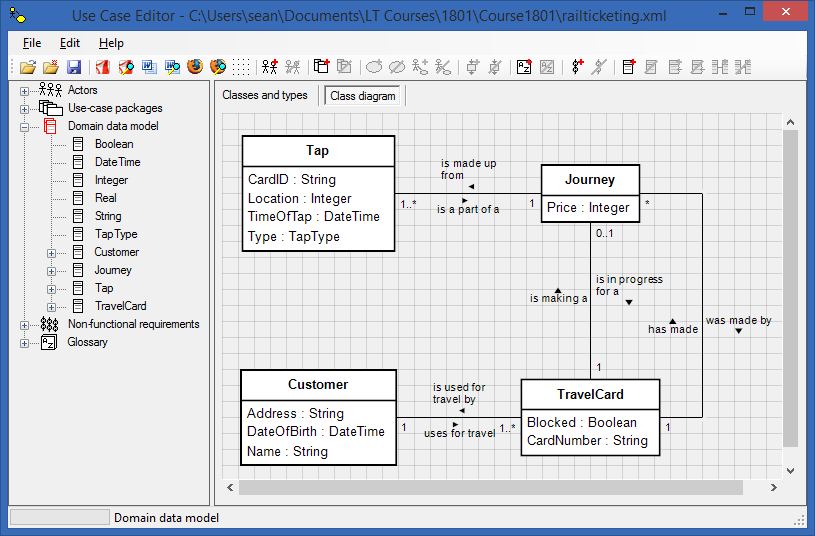
The Use Case Editor autogenerates a data model diagram as a UML class diagram from the types, entities and associations you provide when constructing your domain data model. This diagram can be viewed by selecting the 'Domain data model' node in the treeview, then selecting the 'Class diagram' tab in the right hand panel. An example of a class diagram is shown below:

Manipulating class diagrams

Although the content of the diagrams can only be set by editing the data model descriptions, the layout can be adjusted from within the diagram pane.

If you click on a class or a type in the diagram, the corresponding item changes colour to red to indicate it has been selected. The item can now be dragged to a different location on the screen. Any connectors that link to the dragged item will be adjusted so that they remain connected to the dragged item.

If you double-click a class or an association, the Use Case Editor will jump to the editing page for the corresponding class or association.

It is possible to reroute the connectors between items. If you click on a connection, the connection line will become red to indicate it has been selected. You may now right click on the connector and a pop-up menu will appear:

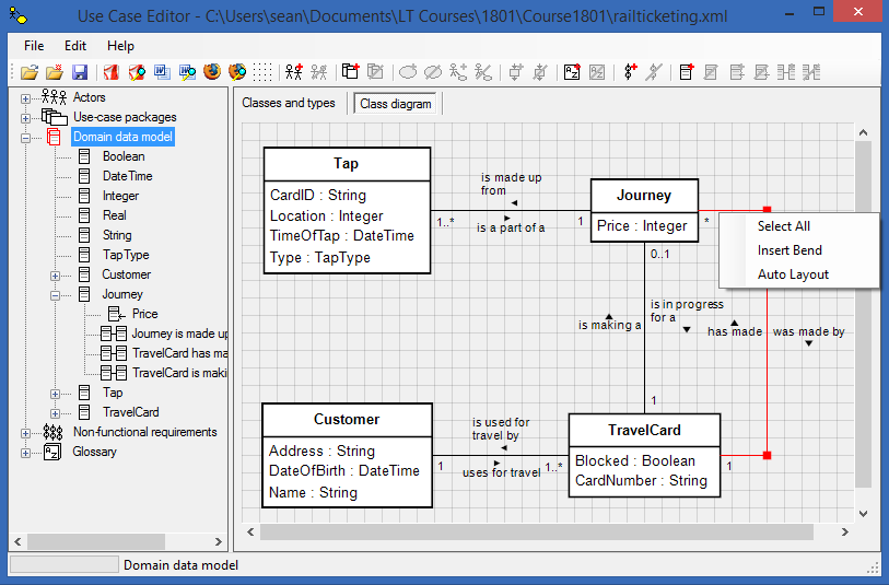
Note that if the right mouse button is clicked on a corner selection grip (the red rectangle at the bend in the connector), the 'Insert bend' menu item is replaced with 'Remove bend'. Select all will highlight the whole diagram in red, allowing you to drag everything on the page. Insert bend will allow you to introduce new bends to the connector so that it can be routed around obstacles on the diagram. Auto Layout lets the Use Case Editor automatically layout the diagram using an internal default algorithm. Note if you select this, any manual layouts you made will be lost. There is no 'undo' for this layout window! As a rule, it is best to use auto layout until you are convinced your model is stable. Then as a last finessing step, adjust the layout of the class diagrams before publication of output documents. The layout algorithm for class diagrams is particularly difficult to automate, so you are encouraged to tidy up the diagram layout once your data model is pretty final.

Note too that once a connector has been highlighted, the line itself may be dragged, or by dragging the rectangular grips you can relocate the ends of each line segment. Experiment with dragging connectors, and with inserting or removing bends to familiarise yourself with the layout tools.
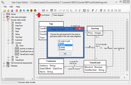
Snap to grid

By default the layout tool snaps graphical elements to a grid that has 16 pixel resolution. This makes it easy to keep lines horizontal and vertical, as well as helps to align actors and use case symbols. The grid resolution can be changed to 8, 16, 24, or 32 pixel resolution as well as being switched off altogether. To change the grid resolution select Edit | Grid spacing ... from the main menu, or click the corresponding toolbar button as shown in the screenshot below: