What is a domain data model?
When gathering requirements, it is helpful to capture several different views of what is required, each view emphasising a different aspect of what the system is intended to contain or do for its users. Use cases give a very good behavioural view of the proposed system, but don't give much information about the underlying business domain information the proposed system is supposed to marshal or manipulate.
the domain data model allows us to capture in the requirements a view of this long term information, together with some idea of how it is structured and interrelated. The domain data model is not intended to be a database design, but a view of the organisation of information from the stakeholder's point of view. Hence there may not be any normalisation, any notion of table constraints or primary key fields, or other such design decision in such a data model. It is intended to be a model that the requirements analyst can use to formulate questions for interview with stakeholders to confirm the information structure, and then to relay the high level data model down to the development team once stable.
A domain model captures things in the business domain that are well understood entities, and identifies what pieces of information about those entities our system needs to store and manipulate. It also identifies the relationships between these entities, that in themselves are part of the system information. These building blocks of data models are described in more detail below.
Domain model types
In a domain model, the building blocks we use are types and entities or classes. A type represents a scalar data type that for the purposes of the model we are constructing does not need to be decomposed further into its constituent parts. Examples of what would normally be considered types might be integers, floating point numbers, character strings, dates or time intervals. The Use Case Editor has a list of built-in types added to every model before the model gets edited by a user. These consist of the following types:
* Boolean, a type that can have the values true or false;
* DateTime, a type that represents a unified date and time for an instant in time;
* Integer, representing a signed whole number of arbitrary range;
* Real, representing a value that can have both integral and fractional parts, also signed and of arbitrary range;
* String, representing an ordered sequence of characters of arbitrary length, and of an unspecified character set but capable of representing all the characters needed for the system being modelled.
In addition to the basic types listed above, the Use Case Editor allows you to define new types of your own. These types will have a descriptive entry in the model, so that you can describe the meaning of the type, its constraints, precision, accuracy, and its units, among other things.
Domain model entities or classes
An entity or class is a compound type in which a number of data items are grouped together because the entity as a whole represents something well understood in the problem domain. The data items it groups together are the pieces of information that parameterise the problem domain entity and for which the system needs to track or manipulate their values. These data items inside each entity or class are knwon as its attributes.
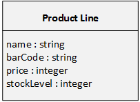
This is best explained by example, so consider our vending machine case study. We might have an entity (class) to represent the product lines that are sold by the vending machine, for which the entity name Product Line might be a good descriptive name. Some examples of the attributes this product line entity might hold could be: the stock level of that product line; the name of the product line; its retail price demanded at the vending machine user interface; its barcode.
For each attribute in an entity, we are also interested in its type. Hence when we model a product line, we will also want to capture the fact that its stock level will be held as an integer, its name as a string, its retail price as an integer, its barcode as a string.
Modelling entities or classes
It is useful to be able to create diagrams of entities, their attributes, and their inter-relationships (associations). UML provides us with an ideal diagram for this purpose, the UML class diagram. The Use Case Editor automatically generates class diagrams from the data you enter describing a data model.
We represent entities as a box divided into two regions horizontally. The top region contains the type name of the entity. The lower larger region contains the list of attributes and their respective types. An example for our product line appears below:
Relationships or associations
As well as capturing the structure of entities, we also model the relationships between them. These relationships represent connections between entity types, and the reason why those entity types would be connected at some point in their lives. The presence or absence of the connection between the entities is itself a part of the information held by the system, as much as the values in the attributes inside the entities are.
The information we capture about the relationship between two entities consists of:
* A reason, verb phrase, or test expression that must be true for the two entities to be connected;
* A reason, or verb phrase that makes sense in the opposite direction between the entities;
* The multiplicity of the association between the two entities in each direction.
As an example, consider a Purchase entity. This represents one transaction made between the vending machine and a customer. The attributes this purchase will record are the cash tendered, the change given, and the time and date at which the purchase took place. However, there should also be a record of which item was purchased. We capture this last piece of infomration as a relationship between the product line entity and the purchase entity, as in the diagram below:
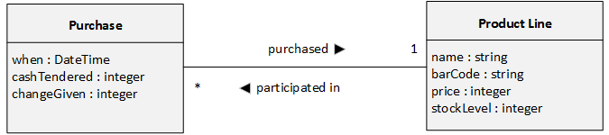
The relationship can be interpreted from the diagram by constructing two sentences from the diagram. First, reading the upper relationship from left to right: "Each instance of a purchase purchased exactly one instance of a particular product line." Second, by reading the lower relationship from right to left: "Each instance of a product line has participated in between zero and many purchases."
Note the interpretation of the multiplicity asterisk symbol as meaning zero to many. There are four multiplicity symbols that are regularly used in domain data models:
|
Symbol
|
Interpretation
|
|
0..1
|
Zero or one, meaning a single optional connection in this direction.
|
|
1
|
Exactly one, meaning that there must always be an instance of a connection in this direction.
|
|
*
|
Zero through many, or any number of connections from the instance at the opposite end of the relationship to instances at this end.
|
|
1..*
|
At least one but possibly multiple connections from the instance at the opposite end of the relationship to instances at this end.
|